

Fleet Angle Analysis in Winching: How Geometry Affects Wire Rope Spooling, Wear, and Bird-Caging
Disclaimer
The technical information provided in this article is intended for educational purposes only and is directed at qualified rigging, lifting, and mechanical professionals. Fleet angle calculations, wire rope selection, and winch system design must always be performed or reviewed by a certified engineer or competent person in accordance with applicable standards (including ASME B30, CSA Z150, and manufacturer specifications). CCR accepts no liability for the application of this information without proper engineering review. When in doubt, consult a qualified professional before operating or modifying any lifting or winching system.
Introduction: The Geometry Nobody Talks About
When a winch or hoist system fails, investigators look at load ratings, rope condition, and operator error. Rarely does the conversation start with geometry — but it should.
Fleet angle is the angular relationship between the wire rope leaving the drum and the centerline of the lead sheave (or the first point of rope contact). It sounds like a minor detail. In practice, it is one of the most consequential variables in wire rope longevity, spooling quality, and system safety.
Understanding fleet angle is not optional for serious rigging professionals. It is foundational.
What Is Fleet Angle?
Fleet angle (θ) is defined as the angle formed between:
- The wire rope as it travels from the drum to the lead sheave or first fleet point, and
- A line drawn perpendicular to the drum axis at the point where the rope departs the drum flange.
              Lead Sheave
              |
              |  ← Rope path
             /
            / ← Fleet Angle (θ)
           /___________________________
          |         DRUM              |
          |___________________________|
          ↑
Perpendicular to drum axisThe Mathematics of Fleet Angle
The fleet angle can be calculated using basic trigonometry:
tan(θ) = D / L
Where:
- D = the horizontal distance from the sheave centerline to the rope’s current position on the drum
- L = the distance from the drum to the lead sheave (the lead distance)
This gives: θ = arctan(D / L)
Worked Example
Assume a drum is 600 mm wide (300 mm from center to each flange), and the lead sheave is positioned 3,000 mm (3 m) from the drum face, directly centered.
- At the drum center: D = 0 mm → θ = 0°
- At the drum flange: D = 300 mm → θ = arctan(300/3000) = arctan(0.1) ≈ 5.7°
| Drum Type | Max Recommended Fleet Angle |
|---|---|
| Smooth drum | 1.5° – 2° |
| Grooved drum | 4° – 6° |
| Lebus® grooved | Up to 6° |
Source: Wire Rope Technical Board (WRTB) and ASME B30.2 guidance.
How Fleet Angle Affects Spooling
Layer-to-Layer Crossover
As the rope reaches the drum flange and begins spooling onto the next layer, it must cross over the previous layer. The fleet angle directly controls the angle at which this crossover occurs. A larger fleet angle means a more aggressive crossover — the rope is forced to climb at a steeper angle, creating localized pressure points and accelerated wear at the crossover zones.
Rope-to-Drum Contact Pressure
The lateral force exerted on the rope as it is deflected by the fleet angle is called the fleet angle side load. This is calculated as:
F_lateral = T × sin(θ)
Where T is the rope tension. Even at 5°, sin(5°) ≈ 0.087 — meaning nearly 9% of the rope’s working tension is being applied as a lateral crushing force against the drum flange or adjacent rope wraps.
Uneven Spooling and Rope Piling
When the fleet angle is too large, the rope does not spool evenly across the drum. Instead of laying in tight, uniform wraps, it tends to pile up near the far flange — creating an uneven, unstable rope bed that worsens with each subsequent layer.
Bird-Caging: When Fleet Angle Becomes Dangerous
Bird-caging is a catastrophic wire rope failure mode where the outer strands of the rope separate and flare outward, resembling the bars of a birdcage. It is most commonly caused by:
- Sudden shock loading that causes the rope core to compress while the outer strands expand
- Reverse bending through sheaves under load
- Improper spooling under excessive fleet angle, which causes uneven strand loading and internal stress concentrations
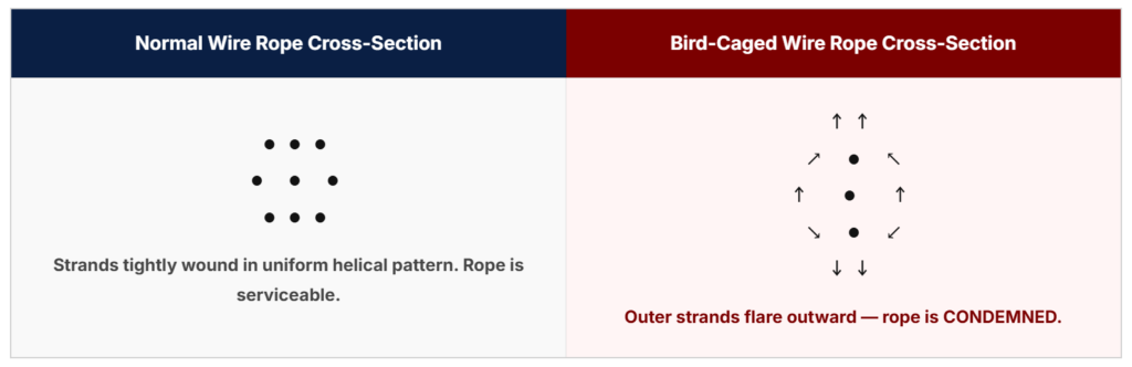
Figure 2: Bird-caging causes permanent deformation of the rope’s helical structure. A bird-caged rope must be removed from service immediately.
When a rope is spooled under excessive fleet angle, the outer strands experience differential tension — some strands are loaded more heavily than others depending on their position relative to the drum. Over repeated cycles, this differential loading fatigues the rope unevenly, weakening the helical structure and making it susceptible to bird-caging under shock load.
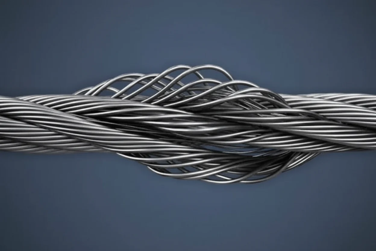
A bird-caged rope is condemned rope. It must never be returned to service.
Minimizing Fleet Angle: Practical Engineering Strategies
1. Maximize Lead Distance (L)
The single most effective way to reduce fleet angle is to increase the distance between the drum and the lead sheave. Doubling the lead distance halves the fleet angle at any given drum position.
2. Use Grooved or Lebus® Drums
Grooved drums mechanically guide the rope into correct spooling position, tolerating larger fleet angles without the rope piling or crossing over aggressively. For applications where fleet angle cannot be minimized, a grooved drum is strongly preferred.
3. Center the Lead Sheave
Position the lead sheave as close to the drum’s lateral centerline as possible. This minimizes the maximum D value and keeps the fleet angle symmetric across both flanges.
4. Use a Spooling Device
Mechanical rope spooling guides (level-wind devices) traverse the drum in sync with rope travel, maintaining near-zero effective fleet angle regardless of drum width or lead distance.
5. Inspect Crossover Zones Regularly
Even within acceptable fleet angle limits, crossover zones accumulate wear faster than the rest of the rope. Establish a documented inspection protocol that specifically targets these zones for broken wire counts and deformation.
Fleet Angle and Multi-Layer Spooling
Fleet angle effects compound with multi-layer spooling. Each layer introduces additional crossover points, and the rope on upper layers is subject to crushing loads from the layers below. The combination of high fleet angle, high tension, and multi-layer spooling is one of the most aggressive wear environments a wire rope can experience.
For critical multi-layer applications, consult the rope manufacturer’s spooling recommendations and consider independent engineering review of the drum geometry.
Summary
Fleet angle is a precise, calculable variable — not an approximation or a “good enough” judgment call. The mathematics are straightforward: θ = arctan(D/L). The consequences of ignoring it are not.
- Keep fleet angle within manufacturer and standard limits (≤ 2° smooth, ≤ 6° grooved)
- Understand that lateral side loads increase with both tension and fleet angle
- Recognize bird-caging as a terminal failure mode linked to improper spooling conditions
- Engineer your lead distance and sheave position before installation, not after problems appear
Wire rope is a precision component. Treat it like one.